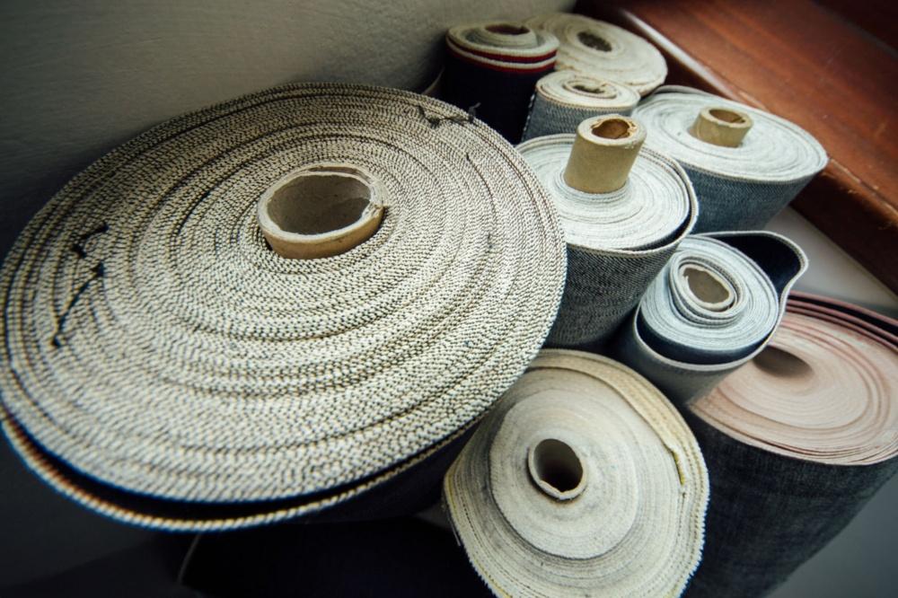
PTFE Coated High Temperature Fabric in Photovoltaic Solar Applications
As a specialized manufacturer of PTFE materials, Jiujiang PTFE Materials Co., Ltd. has witnessed the vigorous development of the new energy industry firsthand. In Q4 2024 alone, over 35% of our production capacity was dedicated to PTFE high-temperature fabrics for the photovoltaic solar sector.
Explore how PTFE high-temperature fabric is the unseen enabler of efficient, high-quality solar panel production and prevents critical defects.
Solar Energy Becomes the Cornerstone of the New Energy Structure
The global transition toward renewable energy sources has catalyzed an unprecedented expansion of the photovoltaic (PV) industry. Driven by a confluence of factors including aggressive climate targets, national energy security policies, and a dramatic reduction in the levelized cost of energy (LCOE), solar power has evolved from a niche technology into a cornerstone of the world’s future energy mix. The International Energy Agency (IEA) and other market analysts consistently forecast exponential growth in annual PV installations, pushing production capacity towards the terawatt-per-year scale. This monumental industrial scale-up places immense pressure on the entire solar value chain, demanding a manufacturing ecosystem capable of sustained high-volume, high-yield, and low-cost production to meet global demand while maintaining economic viability. The long-term performance and bankability of these solar assets, which are expected to operate reliably for 25 years or more, are paramount. This necessitates manufacturing processes that are not only efficient but also impeccably controlled to ensure the durability of every module produced.
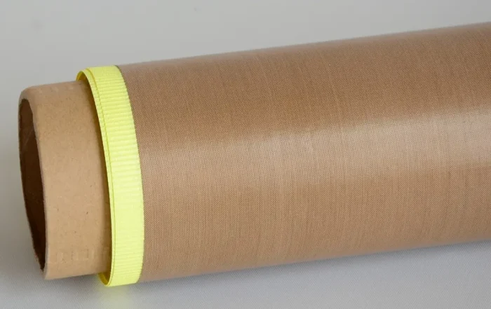
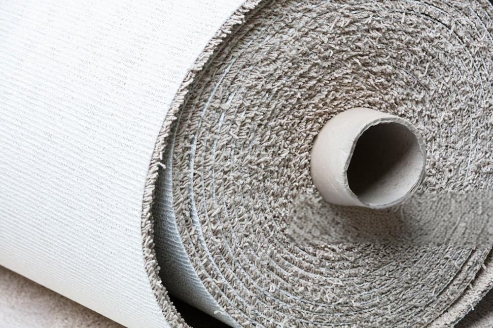
Within this high-stakes manufacturing environment, certain process materials, while not part of the final product, play a disproportionately critical role in determining production efficiency and final module quality. Among the most vital of these is Polytetrafluoroethylene (PTFE)-coated fiberglass fabric. This fabric serves as an indispensable release liner and protective barrier during the PV module lamination process—the critical manufacturing step that encapsulates the delicate solar cells and ensures their long-term protection from the elements. Though its cost is a minute fraction of a finished solar panel’s value, the performance of this fabric has an outsized impact on manufacturing throughput, defect rates, and the ultimate long-term reliability of the solar module itself. It is, in essence, an unseen enabler of modern solar panel production.
Suitability of PTFE High-Temperature Fabric for Solar PV Panels
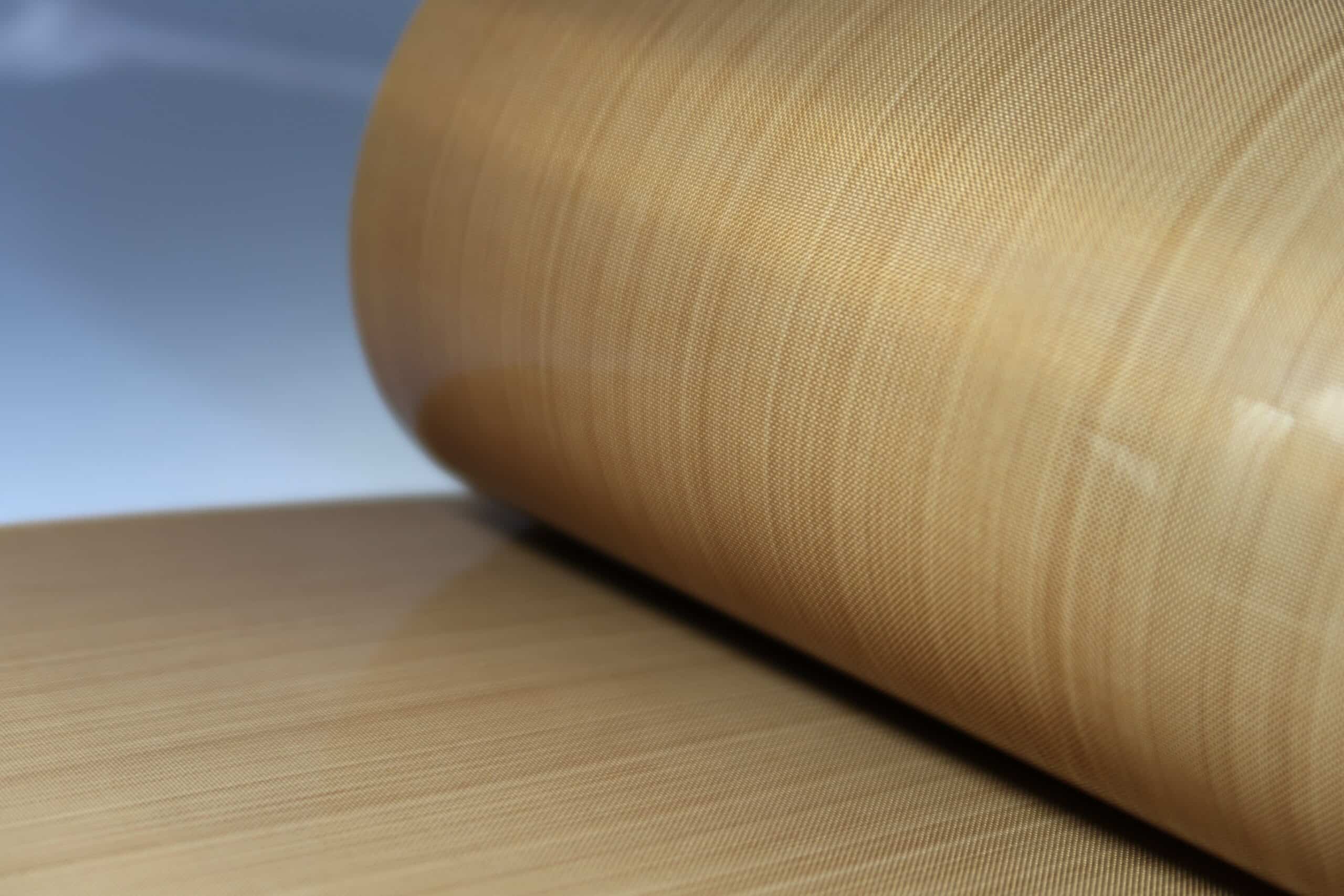
The remarkable suitability of PTFE-coated fiberglass for the demanding environment of solar panel lamination stems not from a single property, but from the engineered synergy of its two constituent components. The material’s architecture combines a mechanically robust substrate with a functionally superior coating, creating a composite that excels where either component would fail on its own. The fabric is fundamentally a composite material, where a woven fiberglass cloth provides the structural integrity and a PTFE coating provides the critical surface properties.
- The substrate of Teflon high-temperature fabric is a woven fabric made of woven glass fiber (“E” glass). E-glass is a continuous filament glass yarn known for its excellent strength-to-weight ratio and thermal stability. The primary function of the glass fiber substrate is to serve as the mechanical “skeleton” of the material. Its core contributions include:
- High Tensile Strength: The fiberglass weave provides exceptional resistance to tearing and stretching, even under the significant pressures applied by the laminator press. This prevents the fabric from deforming or failing during the process.
- Excellent Dimensional Stability: Fiberglass exhibits minimal elongation (often <1%) and maintains its shape and flatness across a wide temperature range. This is critical for ensuring a uniform, wrinkle-free surface is presented to the solar module, preventing imperfections from being imprinted onto the final product.
- Thermal Resistance: While PTFE provides the primary high-temperature surface performance, the glass substrate itself is inherently non-combustible and stable at the process temperatures, ensuring the composite’s overall integrity.
Teflon high-temperature cloth is coated with polytetrafluoroethylene (PTFE), a semi-crystalline fluoropolymer, impregnated and coated on a fiberglass substrate. Pure PTFE is soft, easily deformed, and prone to creep, making it unsuitable for high-pressure applications when used alone. However, with the support of a fiberglass skeleton, its unique surface and thermal properties become extremely valuable:
- Low Coefficient of Friction: PTFE possesses one of the lowest coefficients of friction of any known solid material, giving it its famous non-stick or “release” quality. This is the single most important property for the solar lamination application, ensuring that molten polymers do not adhere to its surface.
- Exceptional Thermal Stability: PTFE has a very high melting point of approximately 327°C and a continuous service temperature range that comfortably extends to +260°C (500°F). This provides a substantial safety margin well above the typical solar lamination process temperatures of 135-155°C, ensuring the coating does not degrade or decompose during repeated thermal cycles.
- Chemical Inertness: PTFE is virtually inert, remaining unaffected by almost all industrial chemicals, acids, alkalis, and solvents. This ensures it is not degraded by any potential byproducts of the lamination process, such as acetic acid that can be released from the EVA encapsulant over time.
This combination is truly synergistic. The fiberglass provides the strength that PTFE lacks, while the PTFE provides the non-stick, chemically inert surface that fiberglass lacks. Together, they form a material uniquely tailored to the harsh conditions of the lamination press.
Synthesizing the properties of the composite material reveals a profile of performance characteristics that directly address the challenges of the solar lamination process:
- Thermal Performance: The fabric is designed to operate continuously in environments ranging from -73℃ to +260℃ (-100°F to +500°F). This broad range ensures it can withstand repeated cycling from ambient factory temperatures to the peak heat of the lamination process and back again without degradation.
- Non-Stick Release: This is the material’s primary function. The extremely low surface energy of the PTFE coating prevents the molten Ethylene-Vinyl Acetate (EVA) encapsulant from forming a chemical or mechanical bond with the fabric. Premium grades feature a particularly high-gloss, super-smooth finish to ensure the cleanest possible release, leaving no residue.
- Chemical and Environmental Resistance: The PTFE coating is hydrophobic and exhibits virtually no water absorption. It is also unaffected by UV, IR, and high-frequency radiation, contributing to its durability and long service life.
- Mechanical and Electrical Properties: The composite material boasts high tensile strength, with typical values exceeding 2100 N/5cm for premium grades, preventing tearing or distortion under laminator pressure. Furthermore, both PTFE and fiberglass are excellent electrical insulators, giving the fabric high dielectric strength (e.g., >1200 volts/mil) and high surface resistivity (e.g., >10¹³ Ohm/sq), enhancing safety in processes involving electrically active components.
PTFE Fiberglass Fabric Grades and Performance Indicators
Due to the outstanding performance of PTFE high-temperature fabric, an increasing number of solar PV panel factories have approached us for procurement. We have received orders for various grades (high, medium, low), with some prices even below our production cost, which was initially confusing. After communication between our engineers and the clients, we realized that not all PTFE high-temperature fabrics are suitable for use in solar PV panels. Different grades of PTFE-coated fiberglass fabric reflect a sophisticated balance between cost, performance, and specific process risks; not every product is suitable for PV panels.
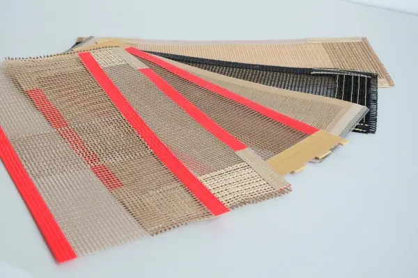
Here we have compiled three common types of PTFE glass cloth that can be used in PV panels. A table comparison can intuitively show their differences:
| Attribute | Premium Grade | Standard Grade | Anti-Static Grade |
|---|---|---|---|
| Typical Thickness | 0.23 – 0.35 mm (9 – 14 mil) | 0.07 – 0.23 mm (3 – 9 mil) | 0.13 – 0.25 mm (5 – 10 mil) |
| PTFE Content | >60% | ~57-60% | ~57-60% + Carbon |
| Tensile Strength (Warp) | >2100 N/5cm | 44 – 96 kg/2.5cm | Varies, similar to Standard |
| Temp. Resistance | -70°C to +260°C | -70°C to +260°C | -70°C to +260°C |
| Surface Resistivity | >1013 Ω/sq | >1013 Ω/sq | 106 – 109 Ω |
| Key Feature | Ultra-smooth, high-gloss, max durability | Cost-effective, general purpose | Dissipates static electricity |
| Primary Use Case | High-volume, high-quality module lamination | General lamination, cost-sensitive lines | ESD-sensitive environments |
If you need to procure PTFE glass cloth for application in photovoltaic solar, you can refer to the performance indicators of these three types.
Application of PTFE High-Temperature Fabric in PV Module Lamination
To fully appreciate the critical role of PTFE-coated fiberglass fabric, one must first understand the lamination process it enables. This manufacturing step is the definitive moment in a solar module’s life, transforming a delicate assembly of individual components into a robust, monolithic unit capable of withstanding decades of harsh environmental exposure.
Principles of PV Module Encapsulation
A standard crystalline silicon photovoltaic module is constructed as a multi-layer “sandwich”. The typical layup consists of: a front layer of high-transmission tempered glass, a sheet of encapsulant film (most commonly Ethylene-Vinyl Acetate (EVA)), the matrix of interconnected silicon solar cells, a second sheet of encapsulant film, and a protective backsheet (typically a multi-layer polymer film).
The primary goal of this structure is encapsulation. The fragile, brittle silicon cells must be hermetically sealed to protect them from the environment. The encapsulant material serves two main purposes. First, it acts as a shock-absorbing cushion, physically supporting the cells and their delicate electrical interconnects. Second, and more importantly, it creates a void-free, moisture-impermeable barrier that prevents water, oxygen, and other corrosive agents from reaching the cells and causing degradation over the module’s warrantied 25-year-plus lifespan.
The Lamination Cycle Deconstructed
- The transformation of this loose stack of materials into a unified, durable module occurs inside a specialized piece of equipment called a solar laminator. The process cycle involves a precise sequence of vacuum, heat, and pressure.
- Loading and Evacuation: The assembled module sandwich is placed inside the laminator chamber. The chamber is then sealed, and a powerful vacuum pump removes virtually all the air. This step is crucial to prevent air bubbles from being trapped within the encapsulant, which would create voids that compromise both the optical transmission and the long-term integrity of the environmental seal.
- Heating and Pressure Application: Once a deep vacuum is achieved, a flexible membrane, typically made of highly durable silicone rubber, is inflated or pressed down from above, applying uniform pressure across the entire surface of the module stack. Simultaneously, a heating platen from below (and sometimes from above as well) raises the temperature of the assembly to approximately 135-155°C. This combination of heat and pressure causes the solid EVA films to melt into a viscous liquid, allowing the polymer to flow and fill every microscopic gap around the solar cells and interconnects.
- Curing: The applied heat does more than just melt the EVA; it initiates a chemical reaction known as cross-linking. Additives within the EVA formulation react, creating strong covalent bonds between the polymer chains. This transforms the EVA from a thermoplastic (which would re-melt when heated) into a stable, durable thermoset elastomer that will remain solid and stable even at the high operating temperatures a solar panel experiences in the field. This curing phase is time-critical, typically lasting around 22 minutes.
- Cooling and Unloading: After the curing is complete, the module is cooled under pressure to solidify the structure before it is removed from the laminator as a single, robust unit.
The Critical Function of the PTFE Release Sheet
The lamination process, with its combination of high temperature and molten, adhesive polymer, creates an environment where unwanted adhesion is a major problem. This is precisely where the PTFE-coated fiberglass fabric performs its essential function.
- Placement: During the loading phase, two sheets of the fabric are strategically placed within the laminator. One sheet is positioned between the top glass surface of the solar module and the laminator’s flexible silicone diaphragm. A second sheet is placed between the module’s polymer backsheet and the hot metal heating platen at the bottom of the press.
- Primary Role – Release Agent: The fundamental purpose of the PTFE fabric is to act as a high-performance, reusable release sheet. Its superior non-stick surface forms a protective barrier that prevents the molten, highly adhesive EVA from sticking to the expensive, precision-engineered surfaces of the laminator itself—namely, the silicone diaphragm and the heating plate. Without this protective layer, cured EVA would quickly foul the machine’s components, requiring aggressive and time-consuming cleaning that would lead to significant production downtime and potential damage to the equipment. The PTFE fabric ensures a clean separation every cycle, enabling the continuous, high-throughput manufacturing required by the industry.
Beyond its role as a process enabler, the PTFE release sheet functions as a critical guardian of final module quality. A failure in its performance, specifically in maintaining a perfectly clean surface, can initiate a chain reaction of defects that leads directly to long-term power loss and safety hazards in the field.
The mechanism for this critical defect begins with improper cleaning of the release sheet. If even microscopic particles of EVA residue from a previous lamination cycle remain on the fabric, they will be transferred and bonded to the front glass surface of the next module during the high-pressure, high-heat process. While this contamination may be invisible to the naked eye upon exiting the factory, its consequences become apparent once the panel is installed outdoors.
Under the influence of daily solar radiation, the small EVA particles on the glass will re-melt and become sticky. These sticky spots act as traps for airborne dust, pollen, and pollution, which become permanently bonded to the glass surface. This creates a small but permanent area of soiling, effectively casting a micro-shadow on the solar cell directly beneath it.
This leads to a dangerous phenomenon known as the “hot spot effect.” A solar cell is a diode; when illuminated, it generates current. However, when shaded, its electrical characteristic flips, and it behaves like a resistor. The current generated by the other, un-shaded cells in the same series string is forced to flow through this small, resistive, shaded area. This causes the energy to be dissipated as heat, leading to a rapid and significant localized temperature increase. A sustained hot spot can damage the solar cell, degrade the surrounding EVA encapsulant, and even burn through the backsheet, resulting in irreversible power loss for the module and, in severe cases, creating a potential fire hazard.
This causal chain—from a dirty release sheet in the factory to a dangerous hot spot in the field—demonstrates a profound connection between a simple, low-level manufacturing protocol and the high-level, long-term performance, safety, and bankability of a multi-decade energy-generating asset. The PTFE fabric is therefore not just a convenience; it is a critical control point for ensuring the quality and reliability that underpins the entire solar industry’s value proposition.
Advantages and Disadvantages Compared to Traditional Materials
Successfully integrating PTFE-coated fiberglass cloth into high-volume, cost-sensitive photovoltaic manufacturing environments requires a combination of optimized operating practices and a clear understanding of its performance relative to potential alternatives. Unleashing the full value of this critical consumable requires rigorous process control, and its continued dominance in the market is demonstrated through direct comparisons of its technological advantages.
To successfully integrate PTFE-coated fiberglass fabric into the high-volume, cost-sensitive environment of PV manufacturing requires optimized operational practices. Below are details compiled by Jiujiang PTFE Materials Co., Ltd. regarding its application in the solar industry.
- Handling and Installation: The fabric’s dimensional stability is a key asset, but it can be compromised by improper handling. It is crucial to keep the fabric as flat as possible during installation into the laminator. Wrinkles or creases must be smoothed out, as these imperfections can be permanently imprinted onto the surface of the solar module during the high-pressure cycle, creating optical defects. Furthermore, creases create stress points that can significantly reduce the fabric’s operational lifespan.
- Cleaning and Reusability: A significant economic advantage of PTFE fabric is its reusability. However, as established, its cleanliness is paramount to preventing module defects. The industry best practice is to utilize at least two full sets of release sheets for each laminator. This allows one set to be in use while the other set is offline, cooling down completely. Once cool, any EVA residue can be carefully brushed or wiped off. This cleaning must be done with care, using non-abrasive materials to avoid scratching or damaging the delicate PTFE coating, which would compromise its non-stick performance.
- Replacement and Downtime Reduction: Despite its durability, the fabric is a consumable material that eventually wears out from repeated thermal and mechanical stress. The non-stick properties degrade over time, increasing the risk of EVA adhesion. Therefore, a regular replacement schedule is a critical part of a preventative maintenance program. Production lines are advised to keep a stock of spare sheets readily available to minimize machine downtime during changeovers. The longevity of the fabric—measured in lamination cycles—is a key performance indicator that directly impacts the manufacturing line’s operational expenditure (OpEx).
A Comparative Analysis of PTFE-Coated vs. Silicone-Coated Fiberglass Fabrics in Solar Panel Manufacturing
In the production of photovoltaic (PV) modules, energy companies commonly use both PTFE-coated and silicone-coated fiberglass fabrics. This analysis provides a comparison of these two materials to guide selection.
- Material Characteristics: Both materials utilize a fiberglass substrate, but their surface coatings impart distinct properties.
- PTFE-Coated Fabric: This material offers a superior non-stick surface with an exceptionally low coefficient of friction. It boasts excellent chemical resistance and a higher maximum continuous operating temperature, typically up to 300°C (570°F). It is also relatively more rigid compared to its silicone counterpart.
- Silicone-Coated Fabric: This fabric provides good non-stick performance, but its surface is more “rubbery” with a higher coefficient of friction than PTFE. It is significantly more flexible and demonstrates better crease resistance. Its chemical resistance is moderate, and it has a lower maximum continuous temperature, generally around 260°C (500°F).
- Application Suitability: For the specific and demanding conditions of solar panel lamination, subtle differences in performance become critical. The process involves molten, highly adhesive EVA (Ethylene Vinyl Acetate) polymer and requires robust resistance to any potential outgassing or byproducts. In this context, the superior release capability of PTFE is not just a minor improvement—it is a critical requirement for ensuring a clean, defect-free process cycle after cycle. The higher temperature threshold of PTFE also provides a greater safety margin, ensuring material integrity even during process fluctuations. While the flexibility of silicone is an advantage in applications like flexible insulation jackets, it is less critical in the controlled-pressure environment of a laminator, where the dimensional stability and premium release of PTFE are paramount.
- Economic Rationale: The choice between these two materials illustrates a classic engineering-economic trade-off. Silicone-coated fabric typically has a lower upfront cost, which can be attractive to manufacturers focused on minimizing initial expenditures. However, the solar industry operates on a high-capital, high-throughput manufacturing model where the cost of failure is substantial. Contamination of a laminator due to poor release properties necessitates unscheduled downtime for cleaning, which can quickly negate any savings from using a cheaper material. More significantly, the cost of a batch of scrapped modules due to surface defects—or worse, warranty claims and reputational damage from in-field failures caused by hot spots—far outweighs the cost difference between the two fabrics. Therefore, the higher initial cost of PTFE fabric is widely regarded as a necessary investment to mitigate these larger operational and financial risks, making it the more economically sound choice for reliable, high-yield production.
The table below provides a direct comparison of these materials for solar lamination applications.
Table 2: Performance Comparison of PTFE-Coated vs. Silicone-Coated Fiberglass
| Property | PTFE – Coated Fiberglass | Silicone – Coated Fiberglass | Rationale for Solar Lamination |
|---|---|---|---|
| Non – Stick / Release | Exceptional | Good | Essential for clean release from molten EVA. PTFE’s superiority is the critical deciding factor. |
| Max Temperature | ~300°C (570°F) | ~260°C (500°F) | Provides a larger safety and process window for the lamination heating cycle. |
| Chemical Resistance | Excellent | Moderate | Important for resisting potential byproducts from EVA degradation (e.g., acetic acid) over many cycles. |
| Flexibility | Good | Excellent | Less critical inside the laminator press; dimensional stability and surface properties are more important. |
| Cost | Higher | Lower | The performance benefits, higher yield, and significant risk reduction offered by PTFE justify the higher initial cost. |
Other Roles of PTFE-Coated Fiberglass Fabric
The unique properties of Teflon-coated glass cloth also make it a valuable material in other steps of the solar and electronics manufacturing process. For example, silicon wafers undergo multiple wet chemical cleaning and etching steps before solar cell assembly. Solid PTFE’s high purity, chemical inertness, and contamination-free surface make it an ideal material for wafer carriers and baskets, which safely transport and secure these delicate wafers in highly corrosive chemical baths.
Furthermore, in fully automated lamination lines, components pass through multiple heating and cooling zones. Textured PTFE-coated glass cloth is often used in conveyor belts for these systems. This material offers the necessary heat resistance for production environments, while its customizable texture provides the appropriate friction to ensure smooth, slip-free component transport.
Beyond producing PTFE high-temperature fabric, Jiujiang PTFE Materials Co., Ltd. dedicates over 50% of its capacity to PTFE conveyor belts. If you are interested in PTFE conveyor belts, please contact our engineers. We offer complimentary samples.